Production-Grade Neural Camera–LiDAR Calibration
End-to-end 6-DoF online calibration—from 500+ GB of multimodal sensor data to TensorRT deployment in an onboard C++ system
As sole technical owner, I took a learning-based system for online 6-DoF camera–LiDAR extrinsic calibration from initial requirements to production deployment. I independently designed and implemented its core data, geometry, model, training, evaluation, and runtime components, spanning fleet-scale sensor processing, geometric validation, multimodal learning, ONNX/TensorRT optimization, and onboard C++ integration.
Even a small camera–LiDAR offset corrupts projection geometry and propagates error into downstream perception.
Fuse RGB appearance with rasterized depth and intensity while preserving camera identity and 3D geometric constraints.
From quality-gated fleet logs to TensorRT inference, robust aggregation, health diagnostics, and sensor-rig generation.
Problem & operating context
Camera–LiDAR misalignment degrades the geometric consistency required by downstream perception. Manual calibration is costly to repeat across a production fleet and difficult to monitor continuously. This system turns calibration into an automated, observable onboard capability: it selects trustworthy sensor observations, estimates an extrinsic correction, aggregates evidence across frames, evaluates calibration health, and produces an updated sensor configuration.
System architecture
Convert raw fleet logs into trusted pairs
- Built a scalable pipeline processing 500+ GB of camera, LiDAR, vehicle-state, and odometry logs into synchronized, reproducible training and evaluation data.
- Implemented temporal alignment, LiDAR motion compensation, virtual-camera rectification, deterministic point selection, and session-level dataset partitioning.
- Added automated gates for motion state, illumination, exposure, blur, point density, depth distribution, and calibration consistency.
- Detected and rejected stale sensor configurations with errors approaching 10°, preventing corrupted geometry from entering training and deployment evaluation.
- Eliminated pose-dependent field-of-view leakage and aligned the Python training pipeline with the production C++ preprocessing contract.
Learn a correction—not an absolute pose
The calibration task is formulated as residual estimation on the rigid-motion group. An imperfect initialization renders the LiDAR observation; supervision asks the network to predict the transformation that returns that observation to the true camera geometry.
Each camera–LiDAR extrinsic is represented as a homogeneous transform. The current estimate renders LiDAR evidence into the camera frame; the network learns the correction, not an absolute pose:
Training perturbs the initialization while holding the true sensor geometry fixed. Every perturbation therefore creates a new projected depth image and a mathematically consistent SE(3) correction target.
Fuse appearance with 3D structure
The network consumes camera RGB, a rasterized LiDAR inverse-depth/intensity representation, and camera identity. Its design separates global rotational reasoning from the local correspondence needed for translation:
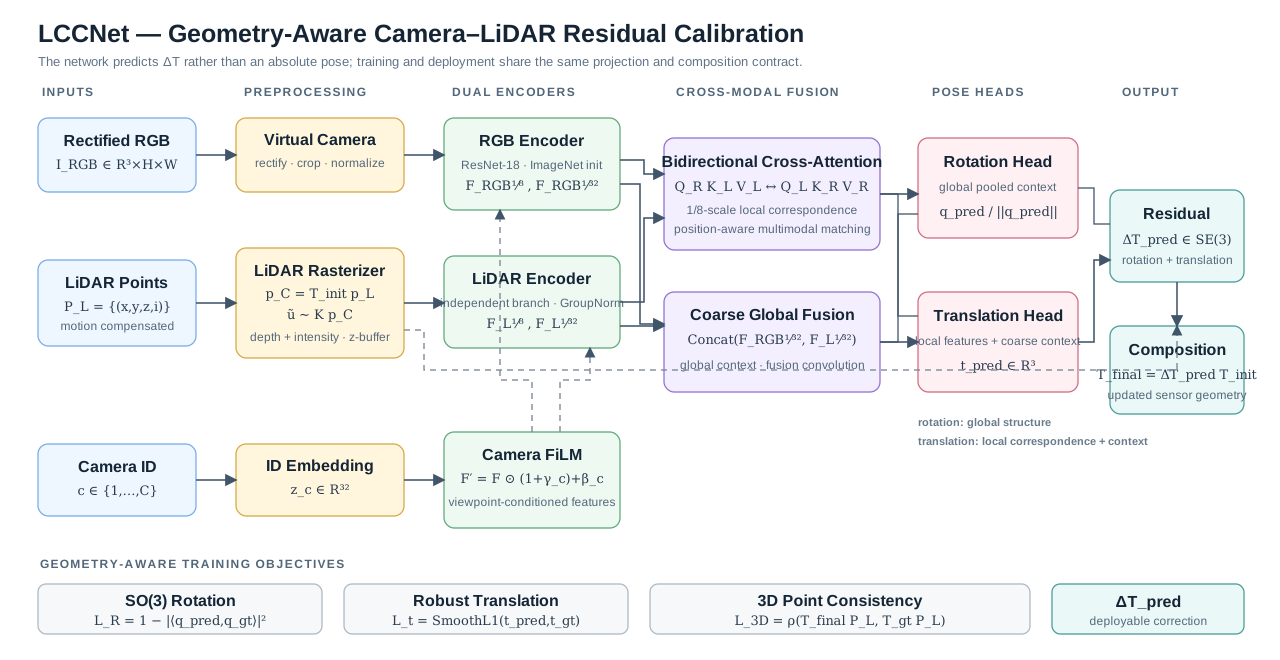
- ImageNet-pretrained ResNet-18 RGB encoder and an independent depth + intensity LiDAR branch with GroupNorm.
- Camera-conditioned FiLM modulation, enabling one network to model multiple camera viewpoints without duplicating the backbone.
- Bidirectional RGB↔LiDAR cross-attention at higher spatial resolution for local geometric correspondence.
- A coarse/global rotation branch and a local-plus-context translation branch for full 6-DoF correction.
- Quaternion normalization, geodesic rotation, robust translation, and 3D point-consistency objectives that supervise the transform in both parameter and geometric space.
Scale the experiment—not the operational risk
I treated training throughput as an end-to-end systems problem, not a model-only optimization. The original pipeline spent most of its roughly 60-hour run time repeatedly executing CPU-heavy point-cloud geometry, projection, and perturbation work. I moved reusable computation out of the hot path and repackaged the dataset into sequential TAR shards for streaming access, reducing a representative single-accelerator run to approximately 20 hours. I then built a world-size-configurable PyTorch DistributedDataParallel runtime that brought the same experiment class below 5 hours—an approximately 13× reduction in iteration time from the initial baseline.
Separate capture range from operating accuracy
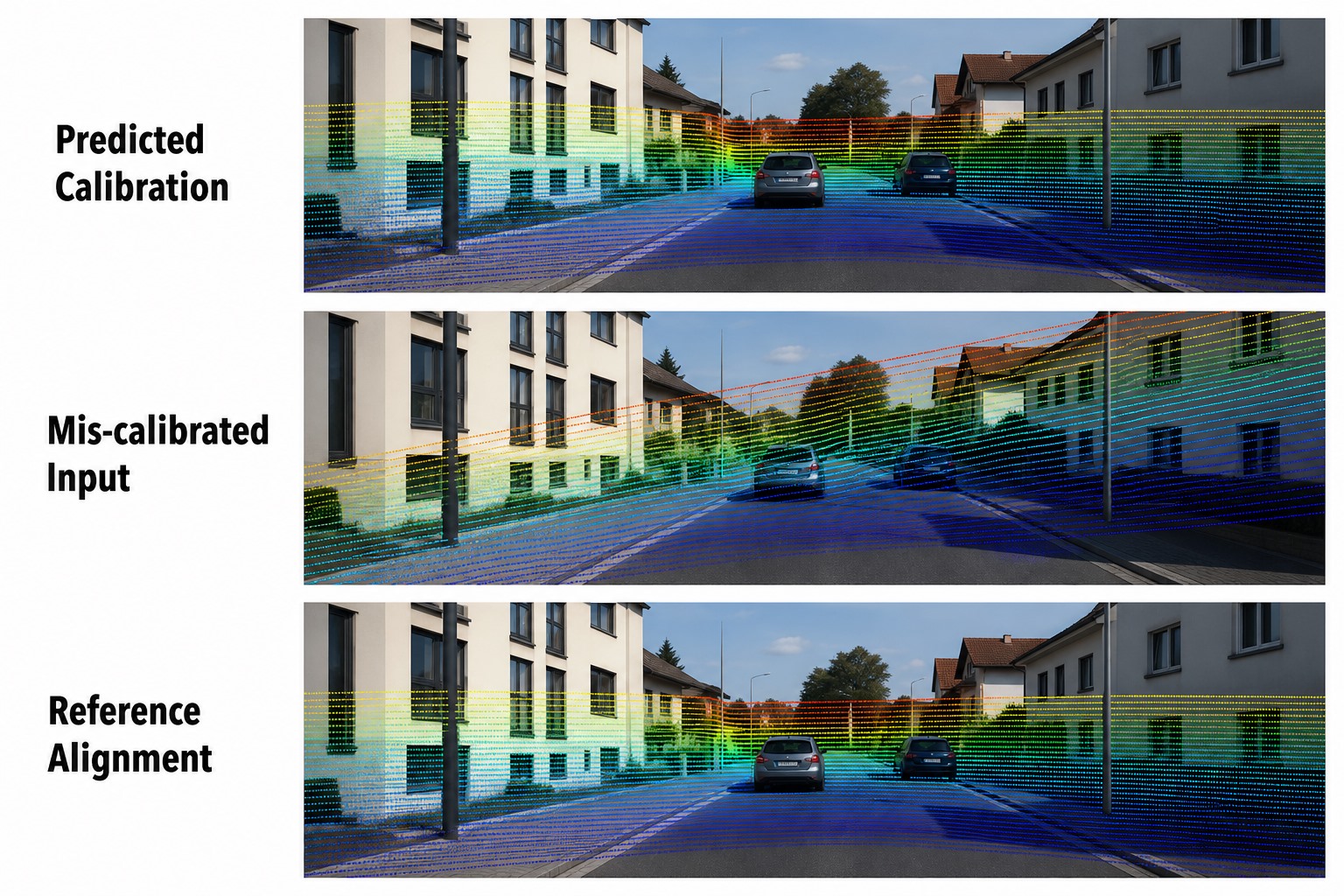
Controlled perturbation evaluation demonstrated recovery from rotational disturbances of up to 10° to approximately 0.5° residual error. This capture range is reported separately from operating-point accuracy: the system reached 0.31° / 3.33 cm on fleet validation and demonstrated sub-degree cross-vehicle generalization, including below 0.6° rotation error on held-out vehicle evaluation.
Ship the same geometry into C++
I productionized the model through PyTorch → ONNX → TensorRT → C++ and integrated it into the onboard autonomy stack. The runtime includes:
- Camera–LiDAR timestamp synchronization and point-cloud motion compensation.
- Shared virtual-camera preprocessing across training and deployment.
- Deterministic depth/intensity rasterization and camera-conditioned inference.
- Iterative correction and robust multi-frame MAD outlier rejection.
- Per-camera calibration health classification and operational diagnostics.
- Safe relative/absolute sensor-pose updates and complete sensor-rig generation.
- Hardware-compatible TensorRT engine selection, inference timing, and recoverable result logging.
Engineering and research depth
Beyond headline accuracy, I built a diagnostic framework for understanding model behavior under domain shift. Controlled ablations and geometric probes isolated bias-dominated error, synthetic-border shortcuts, augmentation-distribution mismatch, and pose-attractor behavior. These findings guided data gates, model selection, and deployment decisions while eliminating expensive but ineffective directions such as naive resolution scaling and variance-only multi-frame aggregation.
Technology
Python · C++ · PyTorch · PyTorch DistributedDataParallel · NCCL · Distributed Sampling · TAR-Sharded Streaming · Geometry Precomputation · Global Metric Reduction · OpenCV · ONNX · TensorRT · CUDA · Protobuf · Docker · Sensor Fusion · 3D Geometry
COMPANION SYSTEMLiLiNet · Neural LiDAR–LiDAR CalibrationView case study →
Selected details are summarized at a high level to respect the confidentiality of production systems and fleet operations.