LiLiNet: Production Neural LiDAR–LiDAR Calibration
Geometry-aware residual calibration—from synchronized point-cloud pairs and distributed training to TensorRT/C++ vehicle deployment
As sole technical owner, I took LiLiNet from initial requirements to production deployment. I independently architected, trained, diagnosed, and shipped the residual-calibration system, which recovers rigid-body alignment between heterogeneous LiDARs from imperfect initial extrinsics and spans multi-session data collection, geometric label auditing, spherical representation and network design, distributed training, controlled evaluation, ONNX/TensorRT optimization, and onboard C++ integration.
Small rotational offsets fragment the unified point cloud and quietly degrade the geometry consumed by downstream perception.
Project both clouds into a shared spherical representation, then expose angular misalignment through circular azimuth correlation.
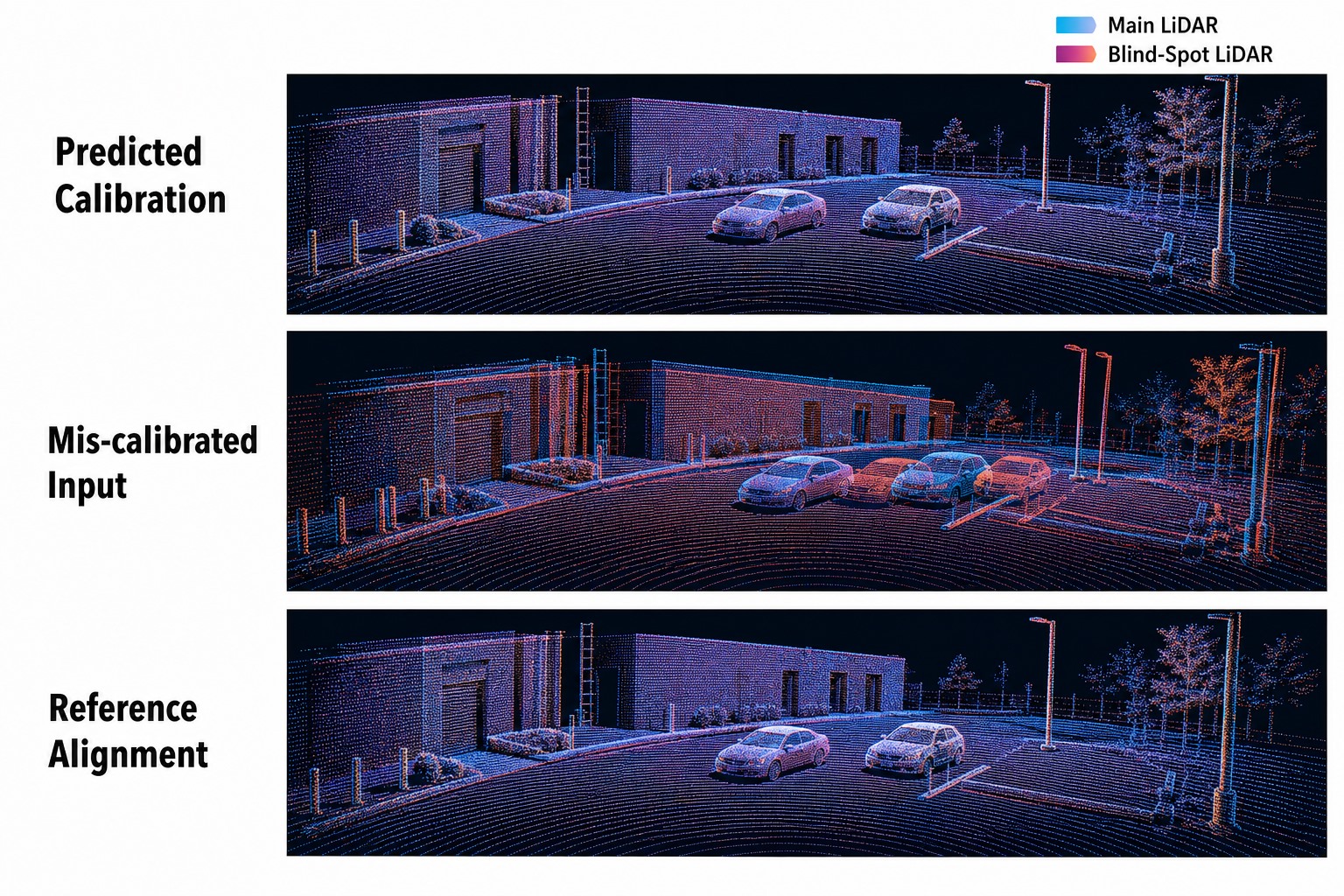
The learned SE(3) residual contracts injected rotational errors of up to 10° to approximately 0.5° within the trained recovery regime.
Problem & operating context
Cross-LiDAR misalignment reduces the geometric consistency of the unified point cloud consumed by downstream perception. Repeating manual calibration for every sensor rig is expensive, while silent drift and incorrect initialization are difficult to diagnose operationally. LiLiNet turns this into an observable production capability: begin with an imperfect extrinsic estimate, select trustworthy synchronized observations, recover the relative pose, aggregate evidence across frames, classify calibration health, and generate an updated sensor rig.
System architecture
Build trustworthy supervision
- Built a reproducible multi-session dataset containing 5K+ synchronized LiDAR pairs, with strict train/validation indexing and deterministic experiment contracts.
- Implemented quality gates for timestamp alignment, ego motion, radial point support, overlap occupancy, shared geometric structure, and corrupted calibration metadata.
- Built robust fleet-level initialization statistics using chordal-SVD rotation averaging and geometric-median translation, while rejecting duplicated, seed-derived, or geometrically inconsistent rigs.
- Developed point-cloud and calibration audits that exposed order-of-magnitude sensor-density anomalies, invalid frame conventions, ranging inconsistencies, and mislabeled evaluation data before they could distort model selection.
Estimate a residual on SE(3)
The initial extrinsics define how the two point clouds should meet in a shared frame. LiLiNet predicts the correction that restores their relative geometry, while rotation quality is measured intrinsically on (SO(3)).
LiLiNet does not memorize an absolute sensor pose. It predicts the rigid-body correction that carries an imperfect initialization back toward the calibrated geometry:
Rotation is evaluated by the geodesic distance on SO(3), not by element-wise matrix error:
Make angular displacement explicit
LiLiNet converts each synchronized point cloud into a full-azimuth 256 × 1536 spherical raster with range statistics, density, intensity, and overlap channels. The architecture is organized around the geometry of the error:
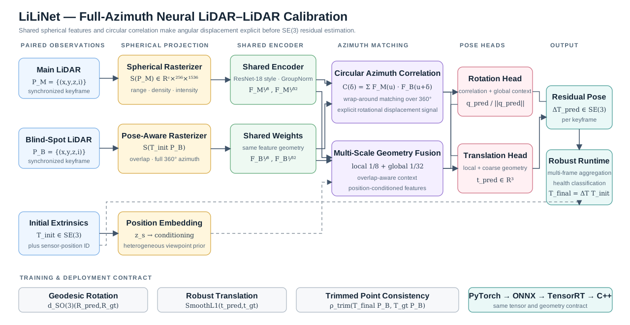
- A shared ResNet-18-style encoder with GroupNorm extracts comparable features across both LiDAR representations.
- Explicit circular azimuth cross-correlation exposes rotational displacement rather than forcing a generic CNN to discover it implicitly.
- A multi-scale translation path combines local 1/8-scale structure with coarse 1/32-scale geometric context.
- Learned sensor-position conditioning and separate normalized-quaternion and translation heads produce a full 6-DoF residual.
- Geodesic rotation, robust translation, trimmed point consistency, yaw/tilt auxiliary objectives, EMA, learned loss weighting, and multi-GPU distributed training stabilize optimization.
Treat scale, evaluation, and recovery as one system
LiLiNet hardens multi-accelerator training beyond basic gradient synchronization. Its PyTorch DistributedDataParallel / NCCL runtime combines vehicle-aware weighted sampling, deterministic per-rank execution, duplicate-free distributed validation, globally reduced metrics, optional synchronized batch normalization, and rank-coordinated operational controls. Strict resume contracts preserve optimizer, scheduler, learned-loss, raw-model, and EMA state so interrupted or extended experiments continue without silently changing model semantics. Multi-accelerator execution increased experimental capacity, while end-to-end profiling localized the remaining throughput ceiling to CPU-side point-cloud loading, spherical rasterization, and nearest-neighbor correspondence construction.
Measure recovery and operating performance separately
Controlled perturbation evaluation demonstrated recovery from rotational disturbances of up to 10° to approximately 0.5° residual error. At the distinct production operating point, LiLiNet achieved +62.5% rotational improvement on session-held-out evaluation. Offline translation improved from 15.20 cm to 4.52 cm (+70.3%), and 208 of 217 evaluated frames improved. Production write-back deliberately preserves the trusted rig translation while applying the learned rotational correction.
Carry the geometry contract onto the vehicle
I productionized the full path through PyTorch → ONNX → TensorRT → C++ and integrated it into the onboard autonomy stack. The runtime includes:
- Stable tensor contracts and numerical parity tooling across Python, ONNX, TensorRT, and C++ preprocessing.
- Hardware-aware TensorRT engine selection across onboard compute variants, with fail-closed compatibility and shape checks.
- Automatic module startup, synchronized keyframe collection, vehicle-motion gating, and geometric BEV-quality screening.
- Independent per-sensor caches, multi-frame inference, quaternion-aware averaging, and MAD outlier rejection.
- Calibration-health classification, operational telemetry, parity dumps, recoverable diagnostics, and complete sensor-rig generation.
- Rotation-only production updates that preserve established translations and handle incompatible sensor-frame conventions explicitly.
Engineering and research depth
The strongest contribution was not a single architecture change, but a rigorous framework for determining why a calibration model succeeds or fails. Controlled probes quantified a projection-mask shortcut, showed that residual error was dominated by stable cross-domain bias rather than frame noise, and demonstrated why simply increasing aggregation or model complexity could not solve new-domain behavior. These findings drove the data gates, noise curriculum, checkpoint-selection protocol, initialization strategy, and deployment decisions while retiring expensive approaches that did not improve the real operating point.
The evaluation protocol also separates session-held-out accuracy from whole-vehicle generalization instead of conflating them—a critical distinction for production ML systems with limited ground-truth calibration data.
Technology
Python · C++ · PyTorch · PyTorch DistributedDataParallel · NCCL · Distributed Sampling · Distributed Evaluation · SyncBatchNorm · EMA Checkpointing · 3D Geometry · Point Clouds · ONNX · TensorRT · CUDA · Eigen · Protobuf · Bazel · Sensor Fusion
COMPANION SYSTEMLCCNet · Neural Camera–LiDAR CalibrationView case study →
Selected details are summarized at a high level to respect the confidentiality of production systems and fleet operations.